 Русский
 English
 Español
 Deutsch
 العربية
 Nederlands
 ไทย
 한국어
 हिन्दी
 Português
Введение
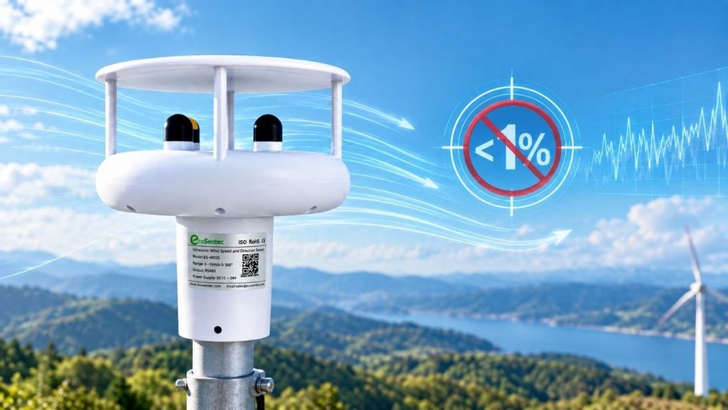
“We need an ultrasonic anemometer with wind speed accuracy of 1%.” We’ve heard this request countless times in my years working with wind measurement technology, and I have to be frank: you can’t achieve this for industrial-grade outdoor applications. This limitation isn’t about product inadequacy. Physical principles and ground conditions that affect every sonic anemometer on the market determine it. We’ll explain why models like the ES-W303 Ultrasonic Anemometer cannot consistently achieve 1% anemometer accuracy across all wind speeds in this piece. We’ll also cover what industry standards actually specify and how to make better decisions when selecting the best anemometer for your application.
What Does 1% Accuracy Really Mean in Sonic Anemometer Specifications
Manufacturers list accuracy specifications for sonic anemometers, but the numbers tell only part of the story. The real meaning depends on whether that percentage refers to the reading or the full scale range.
Percentage of Reading vs Percentage of Full Scale
Accuracy of Full Scale (%FS) means the error stays at a fixed value no matter where you measure within the instrument’s range. Take an instrument calibrated for 100 ln/min with 1.0% FS accuracy. The error equals ±1 ln/min at full scale (100 ln/min). The problem surfaces as flow decreases. That same ±1 ln/min error becomes ±2% of the actual flow at 50 ln/min. You’re looking at ±10% error at 10 ln/min.
Accuracy of Reading (%RD) works differently. The error stays a constant percentage relative to the actual measurement. The same 100 ln/min instrument with 1% RD accuracy shows an error of only ±1% of that flow at 10 ln/min. This performs 10 times better than the FS specification. The variation stays proportional across the entire measurement range.
This difference explains why high-end instruments specify accuracy as % of reading. Mechanical gages couldn’t achieve this due to dial resolution limitations. Modern digital sensors can maintain consistent percentage accuracy across their range.
Understanding Industry Standard Specification Formats
Most sonic anemometer specifications, including the ES-W303 Ultrasonic Anemometer, combine both approaches into a hybrid format: ±0.2 m/s or ±2% of reading, whichever is greater. This format acknowledges a fundamental reality in wind measurement.
Customers request “1% accuracy” and mean 1% of reading. Achieving this across all wind speeds contradicts the physics of ultrasonic measurement in reality. The fixed error component (that ±0.2 m/s) dominates at low wind speeds. The percentage of reading matters more at higher velocities.
That ±0.2 m/s fixed error translates to ±20% accuracy at 1 m/s wind speed. The percentage of reading specification kicks in at ±2% at 10 m/s, which exceeds the fixed error. The “whichever is greater” clause protects manufacturers from overstating performance where physics won’t cooperate.
Wind measurement accuracy specifications reflect a pragmatic compromise between what customers want and what measurement technology can deliver under real-life conditions.
Why This Distinction Matters for Your Application
The accuracy specification format affects your project outcomes directly because wind measurement errors don’t translate linearly into your calculations. Wind forces behave according to speed squared. When wind speed doubles, drag forces multiply by four. This amplification matters for structural engineers designing buildings and crane operators ensuring workforce safety.
The effect intensifies for wind energy applications. Power extracted by a wind turbine follows speed cubed. A wind turbine extracts eight times as much energy when wind speed doubles. Then measurement errors compound in power generation calculations.
Small measurement inaccuracies balloon into substantial calculation deviations. A seemingly minor 1% accuracy error in wind speed measurement amplifies to 3% accuracy in wind load force calculations. A 5% measurement accuracy translates to a 15% deviation when calculating forces or energy output. The mathematical relationship between measurement and application creates this multiplier effect.
Financial stakes run high in wind power projects. Overestimating wind speed by only 10% results in a 33% increase in the projected energy output. This miscalculation makes the payback period appear shorter while the return on investment seems better than reality supports. The University of Leeds examined this problem at 91 wind farm sites in the UK. Their findings revealed overestimation at 73 sites compared to underestimation at just 18 sites. More troubling, overestimation carried a higher standard error of 23%, contrasted with only 10% for sites where wind speed had been underestimated.
Different industries tolerate different accuracy levels based on application requirements. The wind power industry demands the highest accuracy due to the drastic effect wind speed exerts on turbine output. Construction and offshore operations prioritize accuracy for workforce safety decisions. HVAC applications and building commissioning can work with broader accuracy ranges and accept ±1-3% performance.
Structural design faces cost implications from accuracy errors as well. Overestimating wind force during building design leads to overengineered structures that cost more than necessary. Underestimating creates safety risks and potential structural failures.
The difference in accuracy between percentage of reading and percentage of full scale determines whether your anemometer delivers useful data in your specific wind speed range. Wind turbine site assessment requires precision from 4-16 m/s where energy production concentrates. Crane safety monitoring needs accuracy at lower speeds where operations halt. Each application demands you to consider carefully how the accuracy specification performs at your critical measurement points.
The Theoretical Problem: Why Fixed Error Makes 1% Impossible at Low Wind Speeds
Sonic anemometers face an inherent physical constraint that no amount of engineering sophistication can eliminate. The measurement principle itself creates a fixed error floor that dominates accuracy at low wind speeds.
Measuring a Hair with a Ruler: The Fundamental Limitation
To measure low wind speeds with an ultrasonic anemometer is like measuring the thickness of a human hair with a standard ruler. Your measuring tool lacks the resolution needed for the task. Sonic anemometers detect wind by measuring transit time differences in ultrasonic pulses traveling between transducers. Wind speeds that drop below a certain threshold create time differences so minute that electronic noise and measurement precision limits overwhelm the actual signal.
How Ultrasonic Measurement Principle Creates Inherent Timing Errors
Ultrasonic anemometers transmit sonic pulses between transducers and measure the time taken for each pulse to travel across the measurement path. The simple principle follows this relationship: T = L/(c+v), where T represents transit time, L equals the distance between transducers, c denotes the speed of sound, and v indicates air speed along the transducer axis.
Each transducer alternates between transmitter and receiver to isolate wind speed from the speed of sound. It sends pulses in both directions. Wind speed calculation follows: v = 0.5L(1/t1-1/t2). This elegant solution eliminates the need for temperature correction, but the subtraction of two nearly identical time measurements amplifies any timing uncertainty.
The Noise Floor Problem in Sound Wave Transit Time
Modern electronics have advanced. Time measurement resolution can reach nanosecond level, enabling detection of minute transit time differences. Then most ultrasonic anemometers achieve resolution of 1 cm/s, with very low threshold capabilities around 1 cm/s.
Electronic noise and acoustic interference create practical limits, though. Circuit accuracy constraints, electron noise, and acoustic interference produce timing errors. Even with sophisticated signal processing that uses double threshold detection and correlation methods to suppress interference, a fixed timing error persists. To name just one example, a timing error of ±0.01 milliseconds across a typical 0.15-meter transducer spacing translates to ±0.05 m/s wind speed error whatever the actual wind speed.
Accuracy at 1 m/s: Where the Numbers Break Down
That fixed ±0.05 m/s error becomes devastating at low wind speeds. At 1 m/s wind speed, this represents ±5% error. The percentage grows worse as wind decreases further. At 0.5 m/s, you’re looking at ±10% error. This mathematical reality explains why manufacturers specify accuracy as “±0.2 m/s or ±2% of reading, whichever is greater.”
Accuracy at 40 m/s: When 1% Becomes Achievable
That same ±0.05 m/s fixed error shrinks to insignificance at higher wind speeds. At 40 m/s, the fixed error contributes only ±0.125% error. The percentage-of-reading specification dominates at this velocity. A ±2% specification yields ±0.8 m/s error, nowhere near the fixed electronic error. This explains why accuracy specifications approach 1% only at elevated wind speeds where the physics cooperate.
How Real-World Conditions Undermine Laboratory Anemometer Accuracy
Laboratory fine-tuning provides controlled conditions where sonic anemometers perform optimally. Field deployment introduces environmental variables that degrade that carefully fine-tuned accuracy.
Temperature Gradients and Sound Speed Variations
Ultrasonic anemometers remain sensitive to temperature changes, which affect the measurement of travel times along sonic paths. Temperature gradients create sound speed variations that introduce measurement errors. Air temperature changes have the maximum effect on the output signal of piezoelectric emitters. Rapid thermal fluctuations in the atmospheric boundary layer cannot be compensated for fully, even with sophisticated signal processing.
Humidity Effects on Ultrasonic Signal Propagation
Humidity levels affect ultrasonic signal propagation through the air. Relative air humidity shows a minimum effect on piezoelectric emitter output signals compared to temperature. Atmospheric pressure and moisture content still influence measurement accuracy though. Reliable data requires calibration or corrections to account for these factors.
Solar Radiation and Thermal Distortion
Solar heating creates troubling distortions, especially when you have sunny weather. Solar radiation heats the anemometer housing to temperatures more than ten degrees higher than ambient air. This thermal gradient distorts the flow field around the measurement volume and affects sonic path accuracy. Daytime unstable atmospheric conditions make temperature corrections necessary.
Wind Gusts and Turbulence Effect on Measurements
Atmospheric turbulence degrades field performance compared to wind tunnel calibrations. Hot-film anemometers retained their calibration precision during field tests. Sonic anemometers deteriorated though. This difference stems from the effect of atmospheric turbulence on sound wave propagation. Large angles of attack in high turbulence conditions over rough surfaces can exceed the anemometer’s specifications.
Flow Distortion from Mounting Structures
Flow distortion represents the most important error source in field deployments. The anemometer structure itself generates flow distortion. Supporting bars caused maximum wind speed errors of 15% in wind tunnel investigations. Mounting infrastructure compounds this problem. Tower-induced flow distortion can cause wind speed errors in excess of 35% of the real wind speed. Boom mounting on lattice towers produces errors up to ±2% even when following IEC standard design rules.
The Gap Between Controlled Testing and Field Performance
Installation near walls or obstacles demonstrates this gap clearly. An anemometer might measure 5 m/s when true wind speed reaches 5.5 m/s. This represents a 10% difference. Flow distortion error (5-10%) exceeds electronic error (0.5-2%) by an order of magnitude.
Industry Standards: What Accuracy Can You Actually Expect
IEC Standards for Wind Measurement Instruments
The International Electrotechnical Commission (IEC) establishes the standard for wind measurement quality through the IEC 61400 series. IEC 61400-12-1 represents the key standard for wind measurement and specifies correct met mast setup, sensor installation requirements, and quality criteria for data quantity and accuracy. IEC 61400-50-1:2022 defines methods and requirements for instruments measuring wind speed and related parameters. These standards apply to instruments mounted on meteorological masts, turbine nacelles, or turbine spinners.
Accepted Accuracy Ranges in Low Wind Speed Conditions
A cup anemometer offers an accuracy ranging from 1% to 5% under normal conditions. Calibration at ultra-low airspeeds below 1 m/s presents challenges for applications such as indoor airflow measurement and cleanroom monitoring. Anemometer accuracy ranges from ±0.2 percent to ±2 percent, depending on the measurement principle and calibration method. Industry recommendations suggest using a 1-2% accuracy sensor.
Proven High-Precision Ultrasonic Anemometer for Long-Term Field Applications
ES-W303 is high-precision ultrasonic anemometer, developed for applications where reliable and consistent wind measurement is essential. With years of market experience and extensive field application, the ES-W303 has been continuously validated in real-world operating environments. Its ultrasonic measurement technology provides stable wind speed and direction measurements without moving mechanical parts, making it suitable for long-term monitoring and demanding outdoor applications. The proven design, combined with flexible communication interfaces and an integrated heating function, makes the ES-W303 a reliable choice for meteorological monitoring, wind power, transportation, ports, tunnels, and other environmental monitoring applications.
High Wind Speed Range Performance Standards
The IEC 61400 standard requires a 1Hz data sampling rate, one of the most demanding requirements in the industry. Higher accuracy instruments involve higher cost and more stringent installation requirements.
Why Wind Power Industry Accepts These Limitations
The wind power industry tends to be the most demanding due to the drastic effect wind speed exerts on turbine output. The industry accepts these accuracy limitations because they stem from fundamental physical principles rather than manufacturing deficiencies. International networks like MEASNET have developed standards that acknowledge these constraints while ensuring reliable measurements for bankable wind assessments.
What Users Should Focus On Instead of Chasing 1% Accuracy
Chasing headline accuracy specifications misses the bigger picture. Selection criteria extend way beyond that single percentage number on the datasheet.
The Headline Accuracy Number: What Lies Beyond
Accuracy ratings around ±5% serve most applications well. The difference between short-term measurement precision and long-term data reliability matters more than fractional percentage improvements. Your application determines acceptable performance thresholds. Wind turbine site assessment just needs tighter specifications than HVAC monitoring or crop management work.
Fixed Error in Your Wind Speed Range
Match the instrument’s error characteristics to your measurement range. Applications concentrated between 4-16 m/s require you to calculate how the combined fixed and percentage errors perform at your specific velocities. The ±0.2 m/s or ±2% specification format reveals where performance degrades.
Proper Installation Standards That Minimize Errors
Installation quality outweighs sensor specifications. Mount anemometers at least 10 meters above nearby obstructions within a 150-meter radius. Select clear, unobstructed locations that line up with cardinal directions. Environmental sealing (IP66 or IP67 ratings) protects against moisture and dust ingress in harsh conditions.
Short-Term Precision vs Long-Term Stability
Ультразвуковые анемометры require minimal maintenance due to no moving parts. Durable housing and stable electronic components directly affect service life, along with corrosion resistance. Regular calibration schedules maintain measurement confidence, usually on an annual basis.
The Best Anemometer for Your Specific Application
Balance performance requirements against budget constraints. Marine environments need corrosion-resistant materials. Industrial settings may require ATEX or IECEx certifications. Temperature resistance and vibration tolerance match specific operational demands, along with data integration capabilities.
Заключение
To chase 1% accuracy specifications represents an unrealistic goal that distracts from what matters in wind measurement. The physical principles governing ultrasonic anemometers create a fixed error floor that no manufacturer can eliminate. Your focus should change toward proper installation practices, understanding your specific measurement range, and matching sensor characteristics to your application requirements.
We’ve worked with countless clients who achieved excellent project outcomes using instruments with ±2% specifications because they installed them the right way and understood the limitations. The pragmatic compromise between theoretical perfection and practical performance guides you to wiser selection decisions. This piece should help you approach wind measurement with a responsible attitude toward accuracy expectations.